





Why Use Pressure Regulators: Protect Equipment and Ensure Steady Pressure
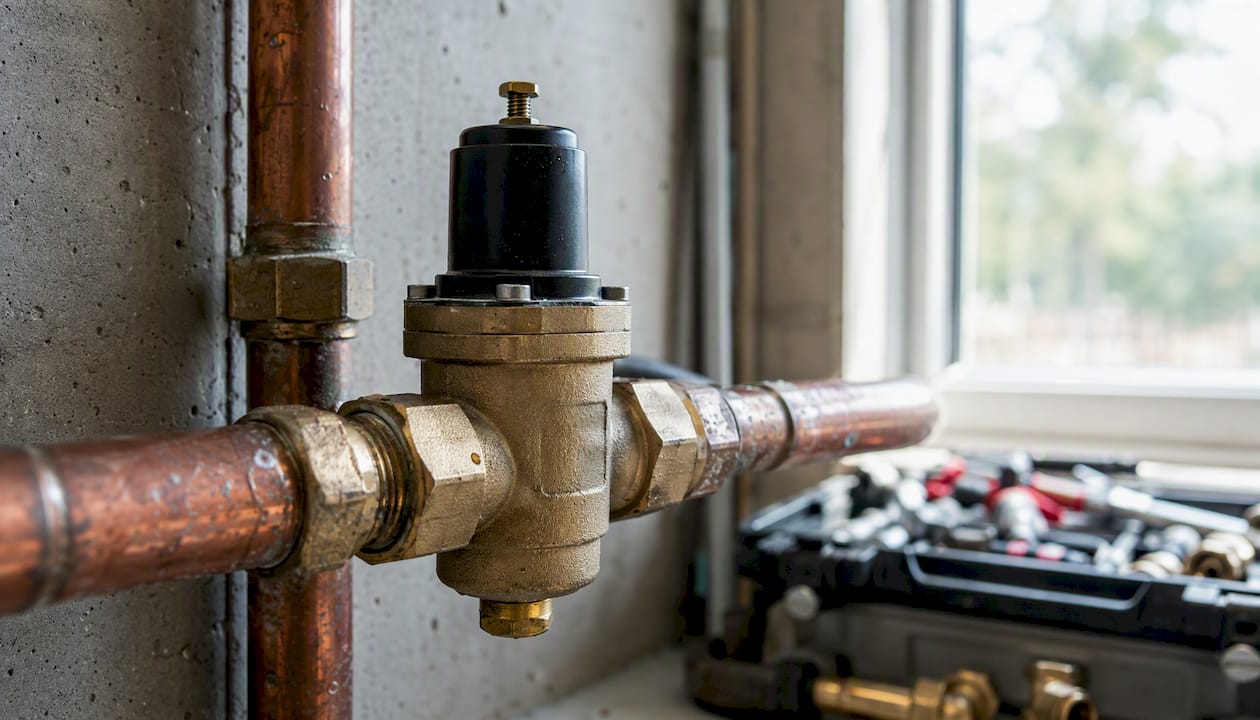
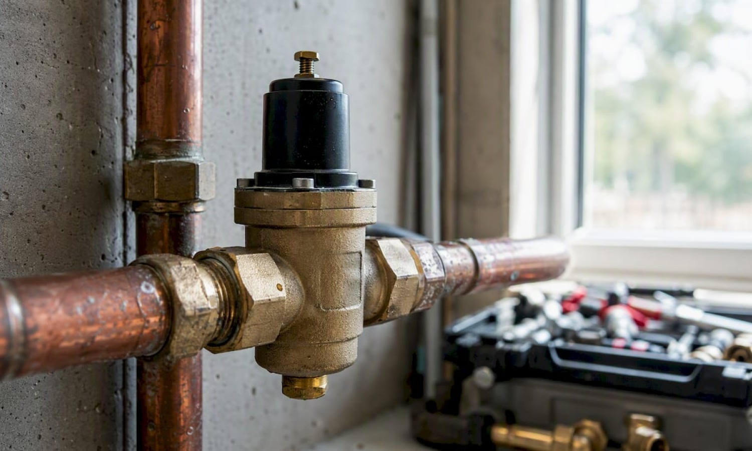
A pressure regulator keeps downstream pressure within a safe, usable range even when supply pressure or demand changes. That single function is why pressure regulators appear in home plumbing, gas cylinders, welding rigs, medical systems, and industrial pipelines. Without one, pressure spikes travel unchecked through a system, damaging valves, fittings, and instruments.
The practical reasons to use pressure regulators come down to four outcomes:
- Equipment protection: prevents overpressure damage to appliances, instruments, and fittings
- Process stability: holds a consistent setpoint so welding, instrumentation, and cooking processes run predictably
- Safety: reduces the risk of leaks, bursts, and hazardous pressure events
- Cost control: lower maintenance frequency and reduced energy waste from running systems at correct pressure
Key Takeaways
Pressure regulators protect equipment, stabilize processes, and prevent hazardous overpressure events — making them a required component in any system where supply pressure exceeds the rated capacity of downstream equipment.
| Point | Details |
|---|---|
| Core function | Regulators hold outlet pressure at setpoint despite changes in inlet pressure or flow demand. |
| Size by Cv, not port size | Match the regulator’s flow coefficient to your maximum flow requirement; oversizing and undersizing both cause performance problems. |
| Two-stage for cylinders | Use a two-stage regulator for welding and gas cylinder applications to maintain stable delivery as supply pressure falls. |
| Filter upstream, always | A 40-micron upstream filter prevents seat contamination, the leading cause of regulator failure. |
| Santehnikasveikals | Supplies valves, gauges, filters, and installation accessories to complete a regulator installation from one source. |
Table of Contents
- How pressure regulators work: core components and the feedback principle
- Main regulator types and when each one fits your system
- Practical benefits of using a pressure regulator in any system
- Where pressure regulators are used: common applications and examples
- Do pressure regulators reduce flow? Understanding Cv and droop
- How to choose the right pressure regulator: a practical checklist
- Installation, testing, and maintenance for reliable regulator performance
- Typical setpoints and numeric ranges for common applications
- A supplier’s perspective on regulator selection and common ordering mistakes
- Pressure regulators and related components at Santehnikasveikals
- Sources
How pressure regulators work: core components and the feedback principle
A regulator holds outlet pressure steady through a continuous negative-feedback loop. The inlet port admits high-pressure fluid. A sensing element (diaphragm or piston) monitors outlet pressure and compares it against a loading element (spring or dome pressure). When outlet pressure drops below setpoint, the sensing element moves the control element (seat or poppet) to open further, increasing flow. When outlet pressure rises, the control element closes to restrict flow.
A regulator is not a shut-off valve and must never be used as one. Its job is continuous modulation — opening and closing the control element in response to downstream pressure changes to hold a set value. Treating it as an isolation device leads to seat damage and setpoint drift.
Three performance terms define how well a regulator holds its setpoint under real conditions:
- Droop: outlet pressure falls as flow demand increases because the sensing element must move slightly to open the control element further. A well-sized regulator keeps droop small.
- Lock-up: when flow drops to zero, outlet pressure rises slightly above setpoint before the control element fully closes. Excessive lock-up indicates a worn seat or oversized regulator.
- Supply-pressure effect (SPE): setpoint shifts as inlet pressure changes. Balanced poppet designs reduce SPE by equalizing inlet-pressure forces on the control element, so the sensing element sees only outlet pressure.
Pro Tip: If your regulator shows significant droop at normal operating flow, the unit is likely undersized for the Cv required — check the flow coefficient before replacing the regulator itself.
Main regulator types and when each one fits your system
Pressure regulators divide into two functional families, then subdivide by stage count and design.
| Type | Control point | Typical function |
|---|---|---|
| Pressure-reducing (downstream control) | Outlet side | Reduces high inlet pressure to a lower, stable delivery pressure |
| Back-pressure (upstream control) | Inlet side | Holds upstream pressure at setpoint; excess fluid passes downstream |
| Single-stage | One reduction step | Simple, compact; setpoint shifts as supply pressure falls |
| Two-stage | Two reduction steps | First stage compensates for supply changes; second holds delivery steady |
Pressure-reducing regulators are the most common type in plumbing, gas distribution, and compressed-air systems. They reduce supply pressure to a usable delivery pressure and hold it there.
Back-pressure regulators protect upstream equipment or processes from pressure buildup. They open to release fluid when upstream pressure exceeds setpoint, functioning more like a pressure-relief path than a delivery device.
Single-stage vs. two-stage: a single-stage design is lighter and less expensive, but its outlet pressure shifts noticeably as cylinder or supply pressure falls. A two-stage design uses a first stage to drop high supply pressure to an intermediate level, then a second stage to regulate delivery. Two-stage regulators are standard for welding and cylinder applications because the first stage absorbs the large pressure swing as a cylinder empties, keeping the torch-side delivery pressure stable throughout the cylinder’s life.
Balanced vs. unbalanced poppet: an unbalanced poppet exposes one face of the control element to inlet pressure, so SPE is higher. A balanced poppet equalizes inlet-pressure forces, reducing SPE and making the regulator more accurate across a wider inlet-pressure range.
| Design feature | Unbalanced poppet | Balanced poppet |
|---|---|---|
| Supply-pressure effect | Higher | Lower |
| Accuracy across inlet range | Moderate | Better |
| Complexity and cost | Lower | Higher |
| Typical use | Low-to-moderate inlet variation | Wide inlet-pressure swings |
Practical benefits of using a pressure regulator in any system
Pressure regulators maintain consistent pressure and protect equipment across every system type. The benefits are concrete and measurable.
- Overpressure prevention: fittings, valves, and appliances carry a maximum rated pressure. A regulator keeps delivery pressure below that limit, preventing cracked fittings, burst hoses, and failed seals.
- Process consistency: a stable setpoint means a welding arc stays steady, a spray gun atomizes paint uniformly, and a laboratory instrument reads accurately. Pressure variation is a direct cause of process variation.
- Leak and burst risk reduction: pressure spikes that travel through unregulated systems can exceed joint ratings in milliseconds. Regulators absorb those spikes before they reach downstream components.
- Energy savings: running a system at the minimum necessary pressure reduces pumping or compression energy. Pressure regulating valves save energy by eliminating the excess pressure that would otherwise be dissipated as heat or noise at throttling points.
- Reduced maintenance frequency: components operating within their rated pressure range wear more slowly. Seals last longer, valve seats stay undamaged, and instrument calibration holds.
- Compliance with design specifications: most appliances and instruments specify an inlet pressure range. A regulator keeps supply within that range, preserving warranty coverage and meeting installation standards. See plumbing standards compliance for the regulatory context.
Pro Tip: Pair every regulator with an upstream filter. Particulate contamination is the leading cause of seat leakage and setpoint drift — a 40-micron filter upstream adds years to regulator service life.
Where pressure regulators are used: common applications and examples
Regulators appear across a wide range of systems. The application determines the regulator type, materials, and accuracy class required.
| Application | Regulator role | Typical inlet pressure | Typical outlet pressure |
|---|---|---|---|
| Residential water supply | Pressure-reducing valve protects fixtures | Municipal main (varies) | 40 psi (2.8 bar) |
| Compressed-air shop | Per-tool regulator matches tool requirements | 150 psi (10 bar) | 60–90 psi (4–6 bar) |
| Welding / gas cylinders | Two-stage regulator delivers stable torch pressure | Up to 2,000 psi (140 bar) | 5–25 psi (0.3–1.5 bar) |
| Medical gas systems | Demand regulator delivers breathing gas at ambient | Cylinder pressure | Near-ambient |
| Natural gas distribution | Staged reduction from transmission to end-user | Transmission line pressure | Appliance delivery pressure |
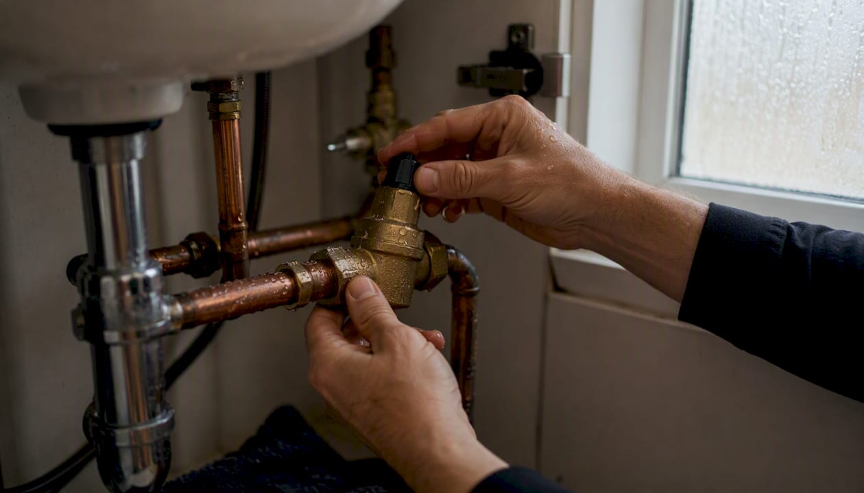
Household plumbing: municipal supply pressure often exceeds what residential fixtures and appliances are rated for. A pressure-reducing valve in the plumbing infrastructure protects washing machines, dishwashers, and faucet cartridges from overpressure damage and reduces water consumption by limiting flow to design pressure.
Compressed-air workshops: a single compressor feeds multiple tools with different pressure requirements. Per-tool regulators let an impact wrench run at 90 psi while a spray gun runs at 30 psi from the same line, preventing damage to lower-rated tools.
Welding and gas cylinders: a full oxygen or acetylene cylinder holds pressure far above what a torch can accept. A two-stage regulator drops that pressure safely, and the gauge on each stage lets the operator monitor both cylinder content and delivery pressure.
Medical and diving: demand regulators in self-contained breathing apparatus (SCBA) and diving equipment reduce cylinder pressure to ambient pressure on inhalation, delivering gas only when the user breathes in. Precision and reliability requirements in these applications are among the highest of any regulator category.
Natural gas distribution: gas travels from transmission pipelines at high pressure through district regulators, then through service regulators at the meter, arriving at appliances at a low delivery pressure. Each stage of reduction is a regulator performing the same pressure-reducing function at a different scale.
Do pressure regulators reduce flow? Understanding Cv and droop
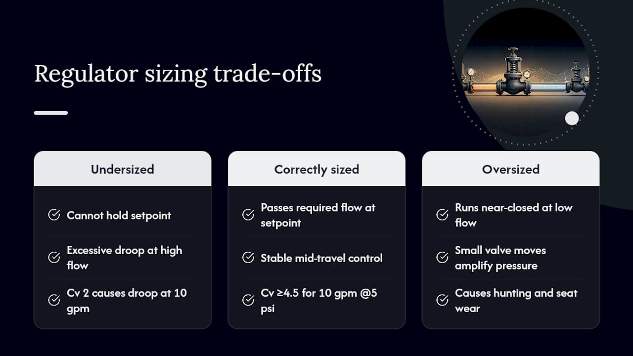
Regulators control pressure, not flow. That distinction matters for sizing. A correctly sized regulator passes the required flow at the required outlet pressure. An undersized one causes excessive droop: as flow demand rises, the sensing element cannot open the control element far enough to maintain setpoint, so outlet pressure falls below the target.
Cv (flow coefficient) is the standard sizing parameter. It expresses how much flow a valve or regulator passes at a given pressure drop. A regulator with a Cv of 1.0 passes approximately 1 gallon per minute of water at a 1 psi pressure drop across it.
A simple sizing check: if your system requires 10 gpm at a 5 psi pressure drop, you need a regulator with a Cv of at least 4.5. Selecting a unit with a Cv of 2.0 will cause the outlet pressure to fall well below setpoint at full flow demand.
Oversizing creates a different problem. A regulator running at a fraction of its rated Cv operates near the closed position, where small movements of the control element produce large pressure changes. This causes instability, hunting (oscillation around setpoint), and accelerated seat wear.
This keeps the control element in its stable mid-travel range and gives headroom for demand peaks.*
Lock-up is the pressure rise above setpoint when flow drops to zero. Excessive lock-up, where outlet pressure climbs significantly above setpoint at no-flow, usually indicates seat wear or a regulator that is too large for the application.
How to choose the right pressure regulator: a practical checklist
Selecting a regulator requires matching six parameters to the application. Missing any one of them leads to poor performance or premature failure.
Selection checklist:
- Maximum inlet pressure (the highest pressure the regulator will ever see at its inlet)
- Required outlet pressure range (minimum and maximum setpoint needed)
- Maximum flow rate and corresponding Cv requirement
- Media type: gas, liquid, corrosive, or clean service (determines body and seal materials)
- Temperature range: fluid temperature and ambient temperature affect seal and spring materials
- Required accuracy: how tight must the outlet pressure stay across the full flow range?
| Parameter | Homeowner / light commercial | Industrial / process |
|---|---|---|
| Inlet pressure | Up to 150 psi (10 bar) | Up to 4,000 psi (276 bar) |
| Outlet pressure accuracy | ±5–10% of setpoint | ±1–2% of setpoint |
| Body materials | Brass, chrome-plated brass | Stainless steel, specialty alloys |
| Seal materials | EPDM, NBR | PTFE, Viton, PEEK |
| Stage count | Single-stage | Single or two-stage |
| Approvals | CE, local plumbing code | ATEX, SIL, ASME, CRN |
Sizing guidance: calculate the required Cv from your maximum flow rate and allowable pressure drop. Swagelok’s selection guidance notes that oversizing is a frequent cause of instability, while undersizing causes droop that makes the regulator appear faulty when it is simply the wrong size.
Material compatibility is non-negotiable. Brass bodies are standard for water and non-corrosive gases. Stainless steel or specialty alloys are required for corrosive media, high-purity gases, or aggressive chemicals. Seal material must be compatible with the fluid: EPDM for water and steam, NBR for petroleum-based fluids, PTFE or Viton for aggressive chemicals.
Venting type: self-venting (relieving) regulators bleed a small amount of downstream fluid to atmosphere when outlet pressure rises above setpoint. Non-relieving types do not vent and are required for toxic or flammable media where atmospheric release is not acceptable.
For smart plumbing systems, also consider whether the regulator needs to coordinate with pressure sensors, expansion tanks, or automated shut-off valves downstream.
Installation, testing, and maintenance for reliable regulator performance
Correct installation determines whether a regulator performs to specification. A well-chosen regulator installed incorrectly will underperform or fail early.
- Orient correctly. Most regulators are designed for horizontal pipe with the spring chamber pointing up. Check the manufacturer’s orientation marking; installing upside-down can cause the sensing element to bind or the spring to load unevenly.
- Install isolation valves upstream and downstream. These allow the regulator to be serviced or replaced without draining the entire system. An upstream valve also lets you depressurize safely before any maintenance.
- Install an upstream filter or strainer. Particulate contamination is the primary cause of seat leakage. A 40-micron or finer filter upstream of the regulator protects the seat and sensing element.
- Support the piping. Do not allow the weight of connected pipe to stress the regulator body. Use pipe hangers or supports within 6 inches of each port.
- Set the outlet pressure with flow running. Adjust the spring tension (turn the adjustment screw) while the downstream system is consuming flow at its normal rate. Setting at no-flow will result in a setpoint that is too high once flow begins.
- Leak-test all connections. Use a compatible leak-detection solution or an electronic detector for gas systems. Never use an open flame. Confirm zero leakage at the body, bonnet, and all threaded connections.
- Verify lock-up. Close the downstream isolation valve and observe whether outlet pressure stabilizes within an acceptable range above setpoint. Excessive pressure rise indicates a seat leak.
- Schedule periodic inspection. Check for setpoint drift, unusual noise (chattering or hunting), and visible corrosion or seal weeping. Diaphragm and piston seals are wear items; replace them on the manufacturer’s recommended interval or at the first sign of drift.
Common failure modes to watch for:
- Seat leakage: outlet pressure rises at no-flow; caused by contamination, wear, or incompatible media
- Diaphragm or piston failure: erratic pressure control or inability to hold setpoint; requires seal replacement
- Spring fatigue: setpoint drifts downward over time; spring replacement restores performance
- Contamination: particulate lodged in the seat causes continuous downstream pressure bleed; upstream filter prevents recurrence
Pressure reducing regulators in HVAC, gas, and water systems require the same maintenance discipline: pair them with appropriate relief valves and isolation valves, and include filters to prevent seat contamination.
Typical setpoints and numeric ranges for common applications
Knowing what setpoints are normal for your application lets you verify that a system is configured correctly.
Residential pressure-reducing valves commonly reduce municipal supply to the 40–60 psi range, protecting fixtures and limiting flow to design pressure. Propane delivery at 11 inches water column (approximately 0.4 psi) is the standard low-pressure setting for most residential gas appliances in North America.
For compressed-air shops, a per-tool regulator at the point of use is more effective than a single regulator at the compressor. Different tools have different pressure requirements, and a single compressor-side setting cannot optimize for all of them simultaneously.
Pro Tip: For propane systems, always use a two-stage setup when the cylinder is outdoors in cold climates. Low temperatures reduce vapor pressure inside the cylinder, and a single-stage regulator will show setpoint drift as the cylinder cools. A two-stage design compensates for this automatically.
Expansion tanks interact directly with pressure regulation in closed heating systems. When a pressure regulator and expansion tank are both present, the expansion tank absorbs thermal pressure increases that would otherwise push the regulator into lock-up or trigger a relief valve unnecessarily.
A supplier’s perspective on regulator selection and common ordering mistakes
The most frequent mismatch seen in orders is selecting a regulator by connection size alone. A 1/2-inch NPT regulator can have a Cv anywhere from 0.3 to 3.0 depending on the internal design. Connection size tells you nothing about flow capacity. Always specify the required Cv alongside the port size.
Homeowners replacing a residential pressure-reducing valve typically need a single-stage, brass-body unit rated to 150 psi inlet with an adjustable outlet range of 25–75 psi and an EPDM diaphragm. Contractors fitting gas or compressed-air systems need to specify media, maximum inlet pressure, and required Cv before selecting a body size.
Stock a set of replacement diaphragms and seat seals for any regulator in continuous service. These are the first components to wear, and having them on hand avoids system downtime. For gas systems, always verify that the replacement seal material is rated for the specific gas in service.
When the application involves corrosive media, high-purity gas, or pressures above 300 psi (21 bar), ask for technical specification assistance before ordering. Selecting the wrong body or seal material for the media is a safety issue, not just a performance one.
Pressure regulators and related components at Santehnikasveikals
Fitting a regulator correctly means having the right supporting components: isolation valves upstream and downstream, a filter or strainer before the regulator, a pressure gauge on the outlet, and a relief device where required. Santehnikasveikals carries valves, gauges, filters, and installation accessories alongside its plumbing and heating product catalog, so you can specify and order the complete assembly from one source.
For homeowners, the most common need is a residential pressure-reducing valve with the associated isolation valves and a downstream gauge. For contractors and engineers, the store’s catalog covers the broader range of components needed for gas, water, and heating system installations. Specification assistance is available for matching regulator flow capacity and pressure ratings to your system requirements. Visit the Santehnikasveikals product catalog to browse available components and request specification support for your project.
Sources
The following sources provide technical depth on regulator selection, operation, and safety:
- Pressure regulator
- What Is a Pressure Regulator and How to Choose One | Swagelok
- Why Are Pressure Regulators So Important? | NVFCL-FITOK Valves & Twin Ferrule Fittings
- The Unsung Hero of Safety and Efficiency: Advantages of Gas Pressure Reducing Valves | KNKE Global
- Ensuring System Safety: The Importance of Pressure Reducing Regulators
Atstājiet komentāru