































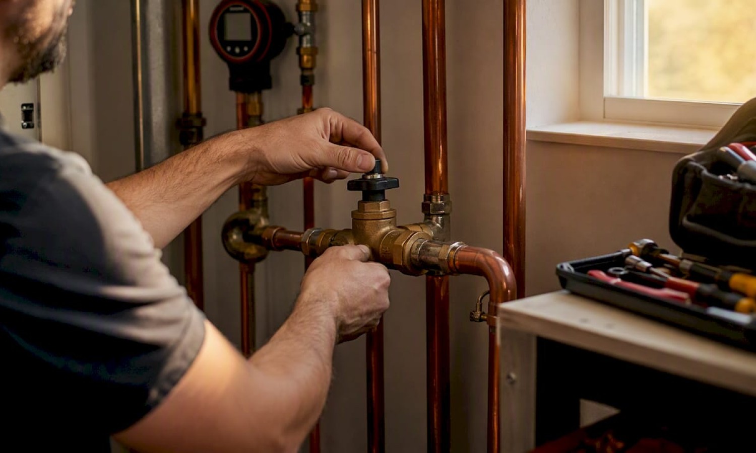

Hydraulic Balancing in Hydronic Systems: A Clear Guide
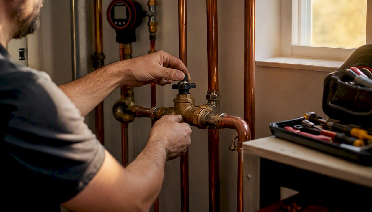
Hydraulic balancing, the industry term for what’s often called hydronic balancing, equalizes water flow so every radiator or terminal unit in a heating or cooling system receives exactly its design flow rate. The result: even room temperatures, reduced pump energy draw, and less wear on circulation equipment.
- Even comfort. Each zone reaches its target temperature without overcooling or overheating adjacent rooms.
- Lower energy use. Pumps run at the correct speed rather than fighting an unbalanced system, cutting unnecessary operating hours.
- Reduced equipment wear. Correct flow rates prevent short-cycling and excess pressure on valves and fittings.
The sections below explain how to recognize an unbalanced system, what measurements technicians take, and what verification data to request at handover.
Key Takeaways
Hydraulic balancing equalizes flow to every terminal unit so the system delivers design performance at the lowest possible pump energy.
| Point | Details |
|---|---|
| Recognize symptoms early | Cold radiators, uneven room temps, and short-cycling all indicate an unbalanced system. |
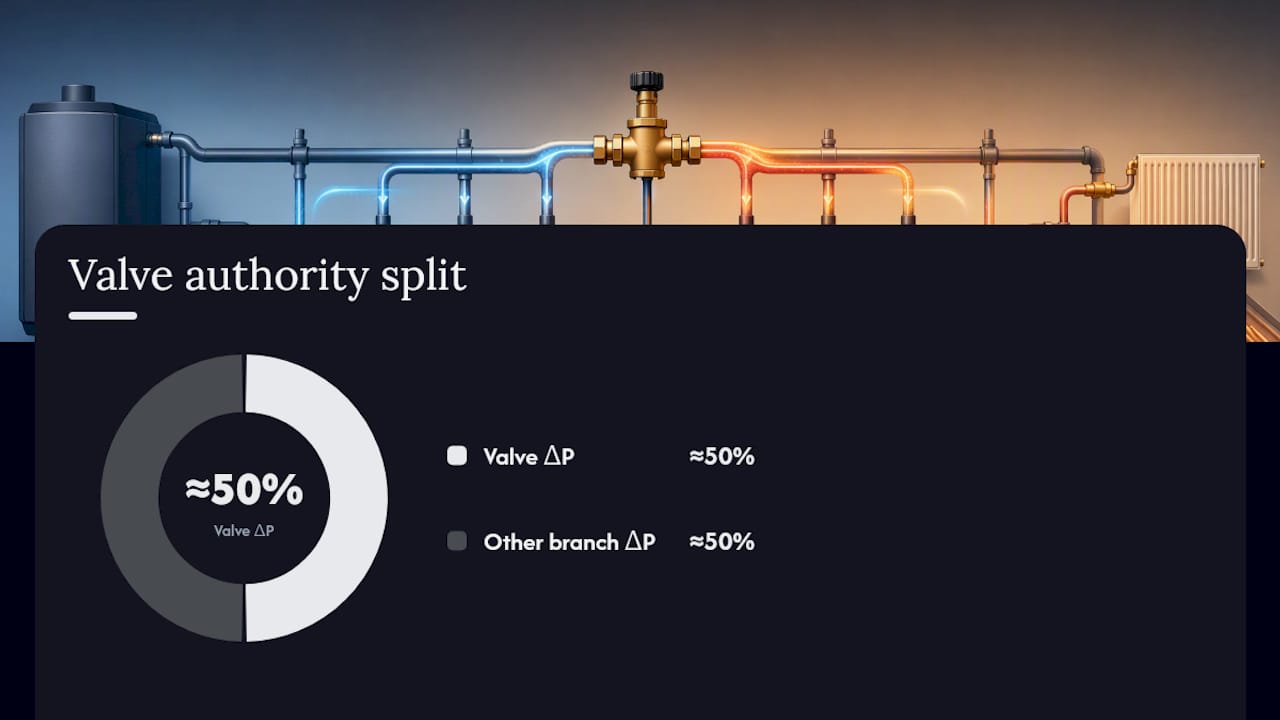
| Valve authority matters | Size balancing valves so their pressure drop is around 50% of branch ΔP for accurate regulation. |
| Use proportional balancing for complex systems | Proportional methods preserve flow ratios when pump speed changes, making them reliable for multi-branch systems. |
| Request a commissioning report | Ask for before/after ΔP, measured %DFR per terminal, valve lock positions, and pump speed setting. |
| Re-check after system changes | Any added or removed terminal, pump replacement, or renovation warrants a new balance check. |
Table of Contents
- What does hydraulic balancing actually mean?
- Why balancing matters for comfort, energy, and equipment life
- How to tell if your hydronic system needs balancing
- Core hydraulic principles behind balancing
- What equipment and methods do professionals use?
- What happens during a professional balancing commissioning?
- How balancing differs between small homes and large buildings
- How long does balancing take, and what does it cost?
- When and how often should you re-check the balance?
- How to verify your installer’s work after balancing
- A practical note on common commissioning pitfalls
- Sources
What does hydraulic balancing actually mean?
A hydronic system moves heated or chilled water from a plant (boiler, chiller, or heat pump) through a network of pipes to terminal units: radiators, fan coils, or radiant panels. Each terminal has a design flow rate, the volume of water per minute it needs to deliver its rated output. Hydronic balancing is the process of adjusting valves and pump settings so every terminal receives that rate simultaneously.
The core problem is that water, like electricity, follows the path of least resistance. A circuit close to the pump and with short, straight pipe runs (a favored circuit) receives more flow than it needs. A circuit farther away, higher in the building, or routed through more fittings (an unfavored circuit) gets starved. Without intervention, the favored circuit overflows while the unfavored one underperforms, regardless of how the thermostat is set.
Physical causes of imbalance include:
- Unequal pipe lengths. Longer runs create more friction, reducing flow to distant terminals.
- Tee geometry and fitting losses. Elbows, reducers, and branch tees each add resistance that varies by circuit path.
- Incorrect valve settings. Factory-default or fully open valves ignore the actual resistance of each branch.
- Oversized or undersized pumps. A pump running above its design point pushes excess flow into low-resistance circuits.
- Unplanned bypasses. Open bypass valves or uncapped connections short-circuit flow before it reaches terminal units.
Understanding these causes helps you visualize why a system that looked fine on paper can produce cold bedrooms and overheated living rooms once it’s running.
Why balancing matters for comfort, energy, and equipment life
An unbalanced system wastes energy in two ways simultaneously: the favored circuits overheat their zones (triggering thermostats to shut off early), while the unfavored circuits never reach setpoint (keeping the boiler running longer). The pump works against mismatched resistances the entire time.
Concrete benefits of a properly balanced system:
- Consistent room temperatures. Supply and return temperatures across branches stay within design tolerances, eliminating hot and cold spots.
- Faster recovery after setbacks. A balanced system redistributes flow proportionally when demand rises, so all zones recover from a night setback at roughly the same rate rather than the nearest zone heating up while distant rooms lag.
- Reduced pump energy. Correct flow distribution allows the pump to operate at or near its design point, often enabling a lower speed setting.
- Shorter boiler run times. When every terminal reaches setpoint on schedule, the heat source cycles less frequently.
- Potential to downsize pump on new installations. A well-balanced design can specify a smaller pump because the system resistance is predictable.
Practical sources note that improved balancing and control can yield energy reductions in the low double digits for retrofit projects, though actual savings depend on the existing system’s condition and the building’s heat loss profile.
How to tell if your hydronic system needs balancing
Most homeowners notice the symptoms before they understand the cause. Run through this checklist:
- One or more radiators stay cold or only warm at the bottom while others in the same system are hot.
- Room temperatures vary significantly between floors or zones despite the thermostat calling for heat.
- The boiler or heat pump short-cycles: it fires, runs briefly, then shuts off and restarts within minutes.
- Circulation pipes make gurgling, rushing, or banging noises, often a sign of high velocity in favored circuits.
- Some radiators take much longer to warm up than others after a cold start.
- Thermostatic radiator valves (TRVs) hunt or oscillate rather than holding a stable position.
A quick homeowner test: With the system running at full demand, feel the supply pipe entering each radiator and the return pipe leaving it. A large temperature difference (supply much hotter than return) suggests the radiator is extracting heat correctly. A small difference on a radiator that’s also lukewarm suggests low flow. Note the warm-up sequence: radiators closest to the pump typically heat first in an unbalanced system. Safety note: pipes can be hot enough to burn. Use the back of your hand briefly, or an inexpensive infrared thermometer.
Simple valve adjustments (partially closing the lockshield valve on overperforming radiators) can help in small domestic systems with fewer than six or eight radiators. For larger systems, persistent complaints after DIY attempts, or any system with zone valves and variable-speed pumps, a professional balance is the right call. You may also want to review whether upgrading older radiators makes sense before investing in a full balance of worn-out equipment.
Core hydraulic principles behind balancing
You don’t need to solve equations to follow a commissioning conversation, but three concepts come up repeatedly.
Design flow (Q). The volume flow rate, typically in gallons per minute (GPM) or liters per hour (L/h), that a terminal unit needs to deliver its rated heat output. It’s calculated from the heat load and the design temperature differential.
Pressure drop (ΔP) and resistance ®. Every pipe, fitting, and valve resists flow. The relationship is ΔP = R × Q², meaning pressure drop rises with the square of flow. Double the flow through a circuit and the pressure drop quadruples. This is why small imbalances in valve settings produce large flow differences. Proportional balancing exploits this relationship: balancing sub-networks pairwise so their flow ratios remain constant even when total system flow changes.
Valve authority. A balancing valve only controls flow accurately if it “sees” a meaningful share of the branch pressure drop. Caleffi’s guidance recommends sizing a balancing valve so its pressure drop at full branch flow is around 50% of the total branch pressure drop, giving an authority of approximately 0.5. Below that threshold, the valve’s position has little effect on actual flow.
| Concept | Plain meaning | Practical benchmark |
|---|---|---|
| Design flow (Q) | Target GPM or L/h for each terminal | Set by heat-load calculation |
| Pressure drop (ΔP) | Resistance the pump must overcome | Measured with a differential-pressure gauge |
| ΔP = R × Q² | Flow changes affect pressure non-linearly | Basis for proportional balancing method |
| Valve authority | Valve’s share of branch ΔP | Target ≈ 0.5 for accurate regulation |
| Index circuit | Highest-resistance path in the system | Starting point for proportional balancing |
The index circuit is the branch with the greatest total resistance. Balancing starts there because it sets the maximum pump head requirement; all other circuits are then throttled to match it.
What equipment and methods do professionals use?
Balancing valve types
Manual commissioning valves (double-regulating or circuit-setter style) have a calibrated scale so a technician can set a specific Kv (flow coefficient) and lock the position. Bell & Gossett’s Circuit Setter, for example, allows pre-calculated settings to be locked before startup, reducing on-site adjustment rounds and lowering pump operating horsepower compared with simple read-and-set procedures.
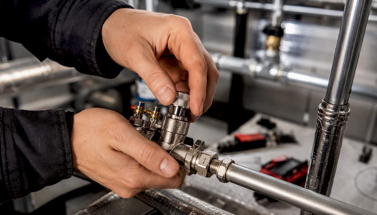
Differential-pressure controllers (DPCs) maintain a constant pressure differential across a branch regardless of system fluctuations. They’re passive devices that protect downstream circuits from pressure spikes when other zones open or close.
Pressure-independent control valves (PICVs) combine a control valve, a differential-pressure regulator, and sometimes a flow-limiting cartridge in a single body. Because they self-regulate, PICVs can eliminate the need for a separate balancing procedure and are particularly useful in variable-flow systems where pump speed changes constantly.
| Device type | Best fit | Key advantage | Limitation |
|---|---|---|---|
| Manual commissioning valve | Small to mid-size systems | Low cost, precise pre-setting | Requires re-adjustment if loads change |
| Differential-pressure controller | Multi-zone systems | Protects branches from pressure swings | Does not control flow directly |
| PICV | Large or variable-flow systems | Self-balancing, no re-commissioning | Higher unit cost, must be correctly sized |
Measurement instruments
Technicians measure differential pressure with a manometer or differential-pressure gauge connected across the valve ports. For flow, ultrasonic transit-time sensors clamped externally to the pipe allow measurement without cutting into the system, making them practical for existing buildings where invasive taps are impractical. Integrated measurement-and-control valves (such as BOA-Control style devices) combine a balancing valve with factory-fitted ultrasonic sensor ports for continuous or periodic readout.
Pro Tip: PICVs or pressure-independent valves often cut commissioning time on large projects because each circuit self-regulates after installation. On a retrofit, however, confirm the existing pipe sizing supports the PICV’s minimum differential-pressure requirement before specifying them.
What happens during a professional balancing commissioning?
A trained technician follows a structured sequence. Here’s what that looks like in practice:
- Pre-check system configuration. Verify all valves are open, air is bled from the system, the pump is running, and the design flow rates for each terminal are documented.
- Identify the index circuit. Trace the highest-resistance path from pump to the farthest or most restricted terminal. This circuit sets the pump head requirement.
- Measure baseline flows and ΔP. Record differential pressure across each branch and, where possible, actual flow (GPM or L/h) at each terminal. Note supply and return temperatures.
- Apply proportional adjustments. Working from the index circuit outward, throttle higher-flow branches so their flow ratio relative to the index circuit matches the design ratio. Proportional balancing preserves these ratios even if total system flow later changes.
- Lock valve settings. Once target ratios are achieved, lock or cap each commissioning valve at its set position. Record the Kv or turn count for every valve.
- Set pump speed. Reduce pump speed (or trim the impeller on fixed-speed pumps) until the index circuit just reaches its design flow. This is the minimum pump energy point.
- Verify at design flow. Re-measure ΔP and flow at each branch. Confirm all terminals are within acceptable tolerance of their design flow rates.
What to record at each step:
- Supply and return temperatures at each terminal (°F or °C)
- Differential pressure across each branch valve (psi or Pa)
- Measured flow vs. design flow, expressed as a percentage of design flow rate (%DFR)
- Valve position (Kv, turns, or scale reading) at lockout
- Pump speed setting (Hz or RPM) at commissioning
Request a written commissioning report with these values. Ask for a re-check after the first heating season, since thermal expansion and settling can shift valve positions slightly.
How balancing differs between small homes and large buildings
Small domestic systems
A single-family home with six to twelve radiators and a single-zone pump is the simplest case. Pre-setting the lockshield valve on each radiator (partially closing the ones nearest the pump) is often enough. Thermostatic radiator valves handle the remaining variation. For systems with fewer than about 20 radiators, static balancing with preset valves is generally sufficient, and a homeowner with basic plumbing knowledge can attempt the lockshield adjustments after watching a reliable tutorial. A simple HVAC system overview can help orient readers who are new to hydronic heating before tackling adjustments.
Larger and commercial systems
Multi-family buildings, schools, and commercial offices have dozens to hundreds of circuits, variable-speed pumps, and multiple heat exchangers. Here, proportional balancing is the standard method because it preserves flow ratios when pump speed changes. For systems with more than roughly 20 radiators or circuits, pressure-independent valves are recommended to ensure reliable automatic flow control as loads shift throughout the day.
Retrofit considerations matter too. Adding a new zone, replacing a boiler, or installing a heat pump changes the system’s resistance map. Any of these changes warrants a re-balance, not just an adjustment to the new circuit.
How long does balancing take, and what does it cost?
Time and cost vary by system size and condition:
- Single-family home (6–12 radiators). A professional balance typically takes 2–4 hours. Cost ranges from roughly $150 to $400 depending on location, access difficulty, and whether any valves need replacement.
- Multi-family building (20–60 terminals). Expect 1–2 days of technician time. Costs range from approximately $500 to $2,000 or more, depending on documentation requirements and valve condition.
- Small commercial (60+ terminals). Full proportional balancing with commissioning reports can run several days and $2,000 to $5,000+, particularly if ultrasonic flow measurement equipment must be rented or if new commissioning valves are installed.
Factors that push costs higher:
- Existing valves lack measurement ports, requiring new commissioning valves.
- Piping is concealed behind finished walls or ceilings, limiting access.
- No design drawings exist, so the technician must map the system from scratch.
- The system has never been balanced, requiring more adjustment rounds.
A quote that doesn’t include a commissioning report is a quote for a workable balance, not an engineered one.
When and how often should you re-check the balance?
A balanced system doesn’t stay balanced indefinitely. Re-check after:
- Any addition or removal of terminal units (new radiator, removed fan coil).
- Boiler, chiller, or pump replacement.
- Major renovation that alters pipe routing.
- Persistent comfort complaints after a previously clean commissioning.
- Annually as part of a scheduled HVAC service, at minimum a visual check of valve positions and pump speed.
Simple maintenance actions between professional visits:
- Confirm lockshield valves and commissioning valves are still at their set positions (they can be accidentally moved during other work).
- Bleed air from high points in the system each fall before heating season.
- Check that thermostatic radiator valves move freely and aren’t stuck open or closed.
- Verify the pump speed hasn’t been manually overridden to a higher setting.
- Inspect for any new bypasses or open drain valves that could short-circuit flow.
Continuous flow monitoring, available through integrated ultrasonic sensors on measurement-and-control valves, provides ongoing proof that balance is maintained after system modernization. Saved measurement logs serve as documentation for warranty claims or future commissioning work.
How to verify your installer’s work after balancing
After a professional balance, run through these steps before signing off:
- Collect supply and return temperatures at each radiator. Use an infrared thermometer. Supply should be consistently close to design temperature; returns should be within the expected differential (typically 20°F for a standard system).
- Confirm warm-up sequence. Start the system from cold. All radiators should reach operating temperature within a similar time window, not in a clear near-to-far sequence.
- Compare installer measurements to the commissioning report. The report should list measured flow or ΔP for each branch. Ask the technician to show you the readings on the gauge or meter before they leave.
- Check valve lock positions. Each commissioning valve should be locked or capped. Photograph the position indicator or scale reading on every valve.
- Record the pump speed setting. Note the Hz or RPM displayed on the variable-speed drive. Any future service call should start by confirming this hasn’t changed.
- Request photos of the manometer or flow meter display at each measurement point. These are your baseline for future troubleshooting.
Pro Tip: Ask the installer to include the index circuit identification, the design flow rate for each terminal, and the measured %DFR in the commissioning report. Without those three items, a future technician has no baseline to work from and will need to re-map the system from scratch.
A practical note on common commissioning pitfalls
The most common on-site problem isn’t a wrong valve setting. It’s a hidden bypass. An open manual bypass valve, a stuck-open zone valve, or an uncapped drain connection can short-circuit flow before it reaches the index circuit, making the system appear balanced at the pump while distant terminals stay cold. Before starting any balance procedure, walk the full pipe route and confirm every bypass is closed and every drain valve is capped.
The second most common issue is a pump running on the wrong curve. A pump set to constant-pressure mode on a system designed for constant-flow will over-pressurize near circuits as zone valves close, pushing the system out of balance dynamically. Confirm the pump control mode matches the system design before touching a single valve.
Sources
Authoritative references for deeper technical detail or commissioning procedures:
- Hydronic balancing - Wikipedia
- Module 183: Proportional balancing for circulating water systems - CIBSE Journal
- Basics of hydronic balancing and types of hydronic balancing | Danfoss
- 2. Balancing valve fundamentals | Caleffi S.p.a.
- Hydraulic balancing of heating and cooling circuits
- Circuit Setter ® Valve Balance Procedure
For U.S. installations, check local mechanical codes (typically based on ASHRAE 90.1 or IMC) and confirm whether a commissioning report is required for permit close-out. Santehnikasveikals carries heating system components and valves for homeowners and contractors working through balancing upgrades or system retrofits.
Atstājiet komentāru