














How to Plan Plumbing Layout: Step-by-Step Drawing Guide

TL;DR:
- A plumbing plan includes fixture schedules, supply and DWV diagrams, riser drawings, and notes necessary for permit approval. Proper sequencing involves finalizing fixture counts and code selection before sizing pipes and selecting water heaters to prevent costly rework. Coordinating wet-wall framing, prefabrication, and thorough documentation reduces delays and field errors in residential plumbing projects.
A permit-ready plumbing plan shows fixture locations, hot and cold supply runs, drainage and vent routing, pipe sizes, cleanout positions, shutoff valves, and a fixture schedule. Before reading further, confirm your plan package includes these minimum deliverables:
- Fixture schedule: count and type of every fixture, with rough-in dimensions
- Supply diagram: hot and cold lines, pipe sizes, pressure zones, and shutoff valve locations
- DWV diagram: sanitary drainage, waste, and vent routing with slope callouts
- Riser or isometric drawing: required for multi-story buildings and most commercial permits
- Materials and notes sheet: pipe material specs, test requirements, and code references
- Permit code references: governing model code (IPC or UPC) and local AHJ amendments
When to hire an engineer: multi-story buildings, public assembly occupancies, process loads, or any project where the AHJ requires a licensed engineer’s stamp. For single-family residential remodels and new construction, a licensed plumber or qualified designer can typically prepare the full set.
Table of Contents
- What does a plumbing plan actually include?
- How to plan your plumbing layout step by step
- What symbols and conventions do plumbing plans use?
- Which tools help you draw a plumbing layout?
- What are the key technical rules for sizing and routing pipes?
- What mistakes do planners most often make?
- What does a US permit submittal require?
- What do annotated bathroom and kitchen layouts look like?
- What to confirm before rough-in or permit submission
- Key Takeaways
- The part of plumbing layout planning most guides skip
- Ready to source fixtures and fittings for your project?
- Useful sources and references
What does a plumbing plan actually include?
A plumbing plan is a set of technical drawings and schedules that documents every component of a building’s water supply, drainage, waste, and vent (DWV) systems. The term “plumbing plan” covers everything from a single-page floor plan overlay for a bathroom remodel to a multi-sheet permit package for a new home. Understanding the scope upfront prevents the most common mistake: submitting an incomplete set and losing weeks to resubmittal cycles.
A permit-ready plan typically contains:
- Floor plan overlays: fixture locations drawn to scale on the architectural floor plan, showing centerline dimensions from walls
- Supply plan: hot and cold water lines, pipe sizes at each branch, pressure-reducing valve location, and all shutoff valves
- DWV plan: drain, waste, and vent lines with slope arrows, pipe sizes, trap locations, and cleanout positions
- Riser or isometric diagram: a three-dimensional schematic showing vertical pipe routing, floor-to-floor connections, and stack locations
- Fixture schedule: a table listing every fixture by room, type, rough-in size, and fixture unit value
- Pipe sizing notes: material callouts (copper, PEX, PVC, ABS), pressure test requirements, and code section references
- Cleanout and access notes: locations of cleanouts, access panels, and service valves
Use cases vary. A full permit submittal for new construction needs the complete package above. A contractor rough-in set for a kitchen remodel may need only the supply and DWV overlays plus a fixture schedule. A DIY homeowner planning a single bathroom addition can often work from a hand-sketched plan with accurate dimensions, provided the AHJ accepts it. Check with your local authority having jurisdiction (AHJ) before investing time in a drawing format they will not accept.
How to plan your plumbing layout step by step
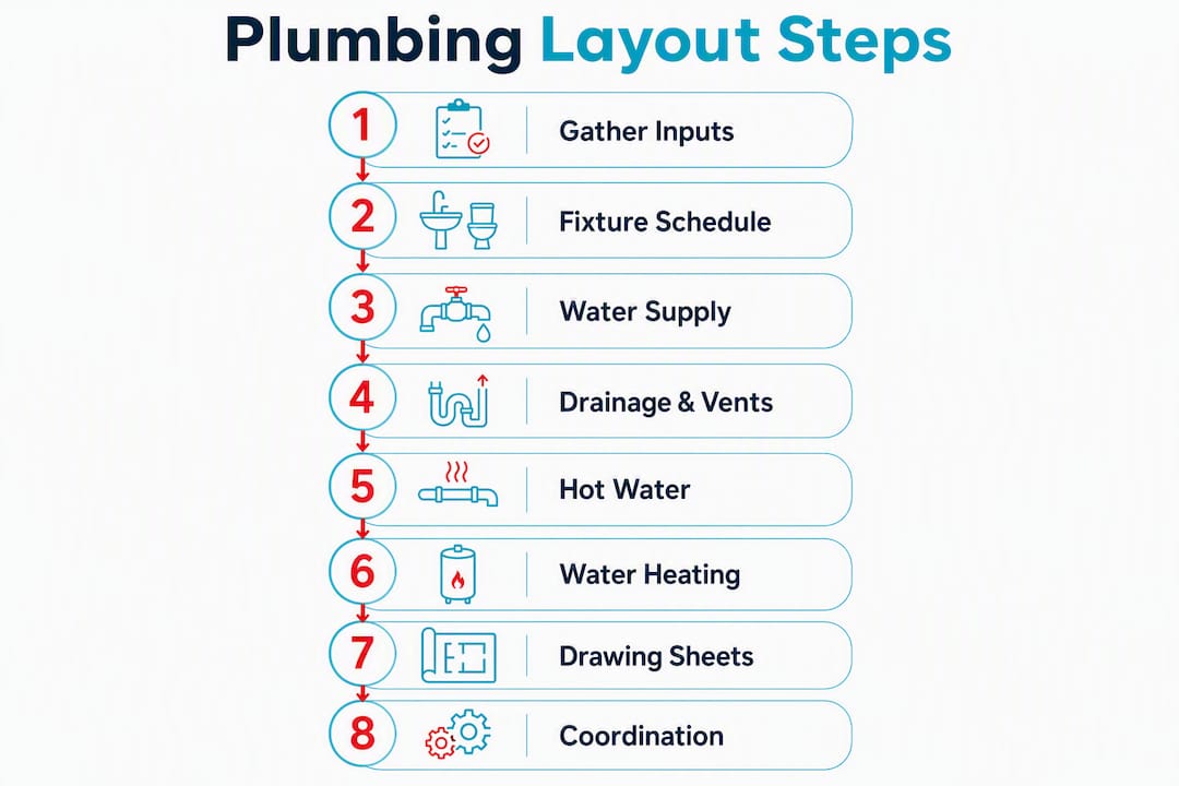
Plumbing design is a chain of dependencies: fixture counts and code selection feed supply sizing, which informs water heater selection and DWV decisions. Reversing that order produces oversized equipment, undersized pipes, or both. Follow the sequence below.
Gather inputs before drawing anything
Collect the architectural floor plans, foundation type (slab-on-grade, crawlspace, or basement), site utility locations and invert elevations, and the governing code. Confirm which model code your AHJ has adopted: the International Plumbing Code (IPC) or the Uniform Plumbing Code (UPC). They differ on fixture unit values, trap arm lengths, and vent sizing tables. Getting this wrong early means redrawing later.
Step 1: Choose your governing code and build the fixture schedule
List every fixture in the project by room. Assign fixture unit (FU) values from your governing code’s tables. A standard water closet, for example, carries a different FU value under IPC than under UPC. The fixture schedule is the foundation of every sizing calculation that follows.
Step 2: Size the water supply
Convert total fixture units to probable peak demand using the Hunter curve or your code’s equivalent demand tables. Identify pressure zones: if the building has multiple floors, calculate static pressure loss per floor (roughly 0.43 psi per foot of elevation). Size the service entry, main, and branch lines to keep cold-water velocity below 8 fps and hot-water velocity below 5 fps to prevent noise, erosion, and pressure loss.

Step 3: Lay out sanitary drainage and vents
Place fixtures on the plan, then route drain lines to the building drain or sewer. Every fixture needs a trap; every trap needs a vent within the code-specified trap arm distance. Stack wet rooms vertically where possible: a bathroom directly above another bathroom shares a single stack, cutting pipe runs and labor significantly. Clustering wet rooms is the single highest-impact layout decision for cost and schedule. Mark cleanout locations at the base of each stack, at changes of direction, and at intervals required by code.
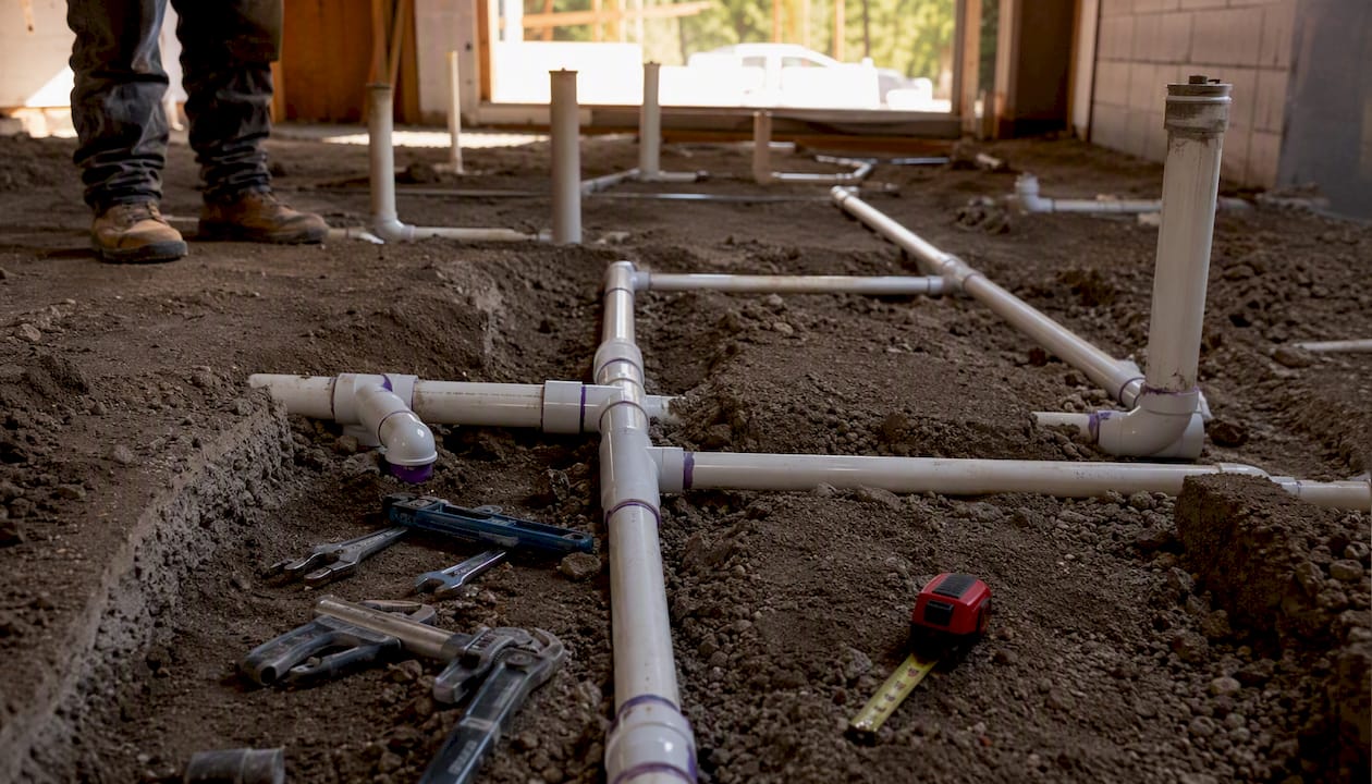
Step 4: Route hot-water distribution
Position the water heater inside or adjacent to the rectangle that encloses all hot-water fixtures. If the stored pipe volume between the heater and the furthest fixture exceeds 0.5 gallons, reconsider the layout or add a recirculation loop. This “hot-water rectangle” heuristic reduces wait times and wasted water. See the cost-saving plumbing layout strategies guide for more on minimizing run lengths.
Step 5: Finalize water heating strategy
Only after fixture counts and simultaneous demand assumptions are confirmed should you size the water heater. Sizing water heaters before finalizing fixture counts is a common and costly sequencing mistake that produces oversized or undersized systems. Decide between tank, tankless, or heat-pump water heating based on peak demand, fuel source, and space constraints. If a recirculation loop is used, size the loop pump and return line at this stage.
Step 6: Create drawing layers and sheets
Separate supply and DWV into distinct drawing layers or sheets. Practical sheet sets used by field professionals include: a plan view overlay for each floor, a dedicated DWV plan, a supply plan, a riser or isometric diagram for vertical coordination, a legend sheet, and a notes sheet covering materials, test pressures, and code references. Label pipe sizes on every run. Add slope arrows on all drain lines.
Step 7: Coordinate with other trades and finalize permit notes
Check every pipe route against structural framing, HVAC ducts, and electrical panels. A 3-inch drain line through a load-bearing stud wall requires a header; a 4-inch stack through a floor joist requires blocking or a manufactured joist hanger. Resolve conflicts on paper before rough-in begins. Add pressure test requirements, inspection hold points, and commissioning notes to the drawing set.
Sequencing rule: Lock fixture counts and code selection before touching pipe sizes. Lock pipe sizes before ordering water heaters. Lock all of the above before scheduling rough-in. Reversing any step in this chain creates rework that costs more than the time saved by starting early.
Pro Tip: If the project repeats the same floor plan across multiple units, prefabricated plumbing trees assembled off-site reduce on-site labor and installation errors. Document the tree dimensions on the drawing set so the fabricator can work from the same sheet the inspector reviews.
What symbols and conventions do plumbing plans use?
Standard plumbing drawings use a consistent set of symbols so that plan reviewers, inspectors, and installers read the same information from the same sheet. Using non-standard symbols without a legend is one of the fastest ways to trigger a plan review comment.
Common fixture and component symbols
- Water closet (WC): oval or D-shape with centerline marks showing rough-in distance from wall
- Lavatory: rectangle or oval labeled “LAV” with hot and cold supply stubs
- Shower: square with a drain symbol (circle with an X) at the low point
- Bathtub: rectangle with drain at one end and overflow notation
- Cleanout: circle with a “CO” label and an arrow indicating access direction
- Vent through roof: circle with “VTR” and the pipe size callout
- Floor drain: circle with a “FD” label and invert elevation
- Grease interceptor: rectangle labeled “GI” with inlet and outlet arrows
- Water softener or filter: rectangle labeled “WS” or “WF” with bypass valve notation
Line conventions
Hot water supply lines are typically drawn as a dashed line or labeled “HW.” Cold water supply lines use a solid line or “CW” label. Waste and drain lines use a heavier solid line. Vent lines use a lighter solid or dashed line, often labeled “V.” Hidden (concealed) lines use a standard hidden-line convention (short dashes). Riser marks show where a pipe transitions from horizontal to vertical with an arrow and elevation note.
Drawing convention: Always include a legend on every sheet. A plan without a legend forces the reviewer to guess your line types, which delays approval. A one-column legend listing each symbol, line type, and abbreviation takes ten minutes to draw and saves days of back-and-forth.
Pro Tip: Use a consistent sheet numbering system: P-1 for the plumbing plan, P-2 for the DWV plan, P-3 for the supply plan, P-4 for the riser/isometric, and P-5 for the legend and notes. Most AHJs expect this format and reviewers find information faster.
Notation standards to follow on every sheet:
- Pipe size callouts: diameter in inches, placed along the pipe run (e.g., “2” PVC DWV")
- Slope arrows: a directional arrow with the slope ratio (e.g., “1/4” per ft") on every horizontal drain run
- Fixture reference numbers: match each fixture symbol to a row in the fixture schedule
- Sheet cross-references: note the sheet and detail number when a section or detail appears elsewhere in the set
Which tools help you draw a plumbing layout?
The right tool depends on the complexity of the project and your drafting experience. A hand sketch on graph paper works for a single-bathroom remodel submitted to a lenient AHJ. A full permit package for a new home typically requires at least 2D CAD.
| Tool category | Best for | Strengths | Limitations |
|---|---|---|---|
| Hand sketch + scale ruler | Simple remodels, DIY planning | No software cost, fast for small plans | Hard to revise, not accepted by all AHJs |
| Entry-level 2D CAD | Residential permits, contractor sets | Precise dimensions, easy revision, PDF export | Learning curve, annual subscription cost |
| BIM platforms | Multi-story, commercial, MEP coordination | 3D clash detection, automatic schedules | High cost, steep learning curve |
| Mobile/tablet field apps | On-site sketching, field markup | Fast, portable, cloud sync | Limited precision for permit-quality drawings |
For non-CAD users, entry-level 2D CAD tools with pre-built plumbing symbol libraries are the practical starting point. Many offer free tiers sufficient for a single-family residential plan. BIM platforms add value when MEP coordination across multiple trades matters, but they are rarely necessary for a straightforward residential layout.
Minimum sheet set for a permit submittal
- Floor plan overlay (one per floor) with fixture locations and centerline dimensions
- DWV plan with pipe sizes, slopes, and cleanout locations
- Supply plan with pipe sizes, shutoff valve locations, and pressure zone notes
- Riser or isometric diagram (required by most AHJs for multi-story buildings)
- Fixture schedule (can be a table on the notes sheet)
- Legend and notes sheet with material specs and test requirements
File formats
Submit PDF for permit review. Provide DWG or IFC files to contractors for field use. Keep a native project file for revisions. Store all versions in a cloud folder with date-stamped file names so the contractor and AHJ always work from the same revision.
For a detailed walkthrough of the installation steps that follow drawing, see the step-by-step plumbing installation guide for practical sequencing from rough-in to finish.
What are the key technical rules for sizing and routing pipes?
Getting the numbers right before drawing saves significant rework. Three rules cover most residential sizing decisions.
Drainage slope
The standard gravity-flow slope is 1/4 inch per foot for horizontal drain lines 3 inches in diameter and smaller. Steeper slopes (1/2 inch per foot) are acceptable for short runs but can cause solids to separate from liquids in longer runs, leading to blockages. Shallower slopes (1/8 inch per foot) are permitted under some codes for 4-inch and larger lines where structural constraints make 1/4 inch impractical. For a deeper look at how slope affects long-term drainage performance, the drainage slopes guide covers the mechanics in detail.
Supply velocity limits
Keep cold-water velocity below 8 fps and hot-water velocity below 5 fps. Exceeding these limits causes pipe noise (water hammer), accelerates fitting erosion, and increases pressure loss at fixtures. Velocity is a function of flow rate and pipe diameter: a 3/4-inch branch serving a single bathroom typically stays well within limits, but a 1/2-inch branch serving multiple fixtures simultaneously may not.
Fixture unit sequencing and pipe sizing
| Design parameter | Standard value | Notes |
|---|---|---|
| Drain slope (standard) | 1/4" per foot | For pipes 3" diameter and smaller |
| Drain slope (large pipe) | 1/8" per foot | For 4" and larger, where permitted |
| Cold-water velocity limit | 8 fps max | Exceeding causes noise and erosion |
| Hot-water velocity limit | 5 fps max | Lower limit due to thermal expansion effects |
| Hot-water rectangle threshold | 0.5 gallons stored pipe volume | Exceeding this warrants recirculation or layout change |
Trap arm length limits and vent sizing follow code tables specific to IPC or UPC. As a general rule, a 1-1/2-inch trap arm cannot exceed 5 feet under IPC before requiring a vent connection. Vent pipe sizing follows the total fixture units connected to the vent stack.
Pro Tip: Use 2x6 framing for wet walls when 3-inch or larger drain lines and vents must pass through. Standard 2x4 walls leave insufficient clearance, forcing field modifications that add cost and delay inspections.
For supply sizing, the water supply planning guide provides residential branch sizing tables and pressure calculation examples.
What mistakes do planners most often make?
Most plan failures fall into four categories. Catching them on paper costs nothing; catching them during rough-in or inspection costs significantly more.
Sequencing errors
- Sizing the water heater before the fixture schedule is complete, producing a unit too large or too small for actual peak demand.
- Routing DWV lines before fixture locations are confirmed with the architect or owner, requiring re-routing when the floor plan changes.
- Ordering pipe and fittings before the drawing set is reviewed, then discovering a code conflict that changes pipe sizes.
Routing and technical mistakes
- Horizontal drain runs without adequate slope, or with slope reversals caused by framing inconsistencies
- Trap arms that exceed code-maximum length, causing siphoning and sewer gas entry
- Missing cleanouts at stack bases, direction changes, or required intervals
- Insufficient vent pipe sizing for the connected fixture unit load
Coordination failures
Ignoring structural framing limits is among the most common field problems. A 4-inch drain line through a 2x10 floor joist requires a manufactured hanger or a structural engineer’s approval. HVAC plenums and electrical panels block chase spaces that look clear on a plan. Resolve these conflicts in the drawing phase, not during rough-in.
Documentation errors
- Missing material callouts (the inspector needs to know whether the drain is PVC, ABS, or cast iron)
- Absent backflow prevention notes on irrigation or hose bib connections
- No pressure test specification on the drawing set
- Pipe size callouts that do not match the fixture schedule’s demand calculations
Inspector red flag: A plan that shows pipe sizes without a fixture schedule or demand calculation gives the reviewer no way to verify sizing. Most AHJs will return the set with a comment requesting the supporting calculations. Include the fixture schedule and a brief sizing note on the drawings from the start.
What does a US permit submittal require?
The two dominant model codes in the US are the International Plumbing Code (IPC), published by the International Code Council, and the Uniform Plumbing Code (UPC), published by IAPMO. Most states adopt one of these with local amendments. Always verify which version your AHJ has adopted before referencing code sections on drawings.
Minimum permit submittal checklist
- Completed permit application with project address, scope of work, and contractor license number
- Fixture schedule with fixture counts, fixture unit values, and rough-in dimensions
- Supply plan with pipe sizes, material callouts, and shutoff valve locations
- DWV plan with pipe sizes, slope callouts, cleanout locations, and vent routing
- Riser or isometric diagram (required by most AHJs for two or more stories)
- Backflow prevention notes for any hose bibs, irrigation connections, or cross-connection risks
- Water heater specifications: capacity, fuel type, relief valve discharge routing, and seismic strapping (where required)
- Pressure test specification: typically 100 psi air or water for supply, and water test for DWV
Inspection sequence
Most AHJs conduct three plumbing inspections:
- Rough-in inspection: all pipes in place, pressure test passed, before walls are closed
- Pressure test inspection: sometimes combined with rough-in; supply lines at test pressure, DWV water-filled
- Final inspection: fixtures installed, all trim complete, no open connections
When to hire a licensed engineer
Hire a licensed mechanical or plumbing engineer when the project involves a building over three stories, a public assembly occupancy, a commercial kitchen with grease interceptor requirements, a medical or laboratory facility, or any system where the AHJ requires a professional engineer’s stamp. For standard single-family residential projects, a licensed plumber or qualified designer can prepare the full permit set. See the plumbing regulations guide for jurisdiction-specific submittal requirements.
What do annotated bathroom and kitchen layouts look like?
Concrete examples are more useful than abstract rules. The descriptions below cover what to show on each sheet for the two most common residential plumbing scenarios.
Annotated bathroom plan
A standard full bathroom (water closet, lavatory, tub/shower) requires:
- WC centerline: 15 inches minimum from side wall to centerline, 21 inches minimum clear in front (IPC)
- Lavatory drain: 1-1/2-inch trap arm, maximum 5 feet to vent connection under IPC
- Tub/shower drain: 2-inch minimum, sloped to drain at the low point of the shower floor
- Vent stack: 3-inch minimum for a bathroom group, shown rising through the roof with a “VTR” callout
- Cleanout: at the base of the stack and at the branch connection to the building drain
- Supply stubs: hot and cold at each fixture, with shutoff valves shown at the supply stub location
Template tip: Draw the bathroom plan at 1/4 inch = 1 foot scale. Show all fixture centerlines, rough-in dimensions, and pipe sizes on the same sheet. A second sheet shows the DWV isometric for the bathroom group. This two-sheet set covers most AHJ requirements for a single bathroom addition.
Annotated kitchen plan
A kitchen plumbing plan covers:
- Sink: double-bowl sink with a 1-1/2-inch or 2-inch drain, P-trap, and vent within code-maximum trap arm distance
- Dishwasher: high-loop drain connection to the sink drain or a dedicated air gap fitting; 3/8-inch or 1/2-inch supply connection
- Garbage disposal: connected to one bowl of the sink drain, with a wye fitting to the drain line
- Floor drain: required in some jurisdictions for commercial kitchens; show invert elevation and trap type
- Supply: hot and cold stubs under the sink with shutoff valves; dishwasher supply from the hot line
Pro Tip: For slab-on-grade construction, show all under-slab drain lines on a separate “under-slab” plan layer with invert elevations at each fixture connection. This sheet is critical for the concrete contractor and the inspector, and it prevents costly slab cuts later.
Template adaptation tips
| Building type | Key adaptation |
|---|---|
| Slab-on-grade | Add under-slab plan with invert elevations; no crawlspace access for later changes |
| Raised floor/crawlspace | Show joist direction and pipe routing relative to framing; note access hatch locations |
| Multi-story stacking | Add riser diagram showing each floor’s connection to the shared stack; note floor-to-floor heights |
| Basement | Show sump pump location and ejector pit if fixtures are below the building drain invert |
For downloadable templates, field-ready plumbing diagram libraries are available through drawing tools that support plumbing symbol sets. Export as PDF for permit submittal and DWG for contractor use.
What to confirm before rough-in or permit submission
Run through this checklist before ordering materials or scheduling rough-in. Each item represents a category of rework that is far cheaper to resolve on paper.
- Confirm utility location: water service entry point, meter location, and sewer invert elevation at the property line
- Verify finished floor elevations at every wet room to confirm drain inverts clear the building drain or sewer
- Confirm foundation type (slab, crawlspace, basement) and joist direction in all areas with horizontal drain runs
- Lock fixture locations with the architect or owner; get written confirmation before drawing DWV routes
- Finalize fixture schedule and material selections; confirm all rough-in dimensions match the specified fixtures
- Request an AHJ pre-application meeting or pre-check if the project is complex or the jurisdiction is unfamiliar
- Confirm shutoff valve locations: main service shutoff, individual fixture shutoffs, and isolation valves for each zone
- Plan cleanout access: every cleanout must be reachable without demolition; note access panel locations on the drawing
Additional site checks before rough-in begins:
- Verify that framing is complete and stud bays are clear of electrical and HVAC conflicts
- Confirm staging area for pipe storage and confirm delivery access for large fixtures
- Check that all permit approvals are in hand before any pipe is cut or installed
Key Takeaways
A permit-ready plumbing plan requires a fixture schedule, separate supply and DWV diagrams, a riser or isometric drawing, and cleanout and test notes, all sized in the correct sequence: fixture counts first, supply sizing next, then water heating and DWV.
| Point | Details |
|---|---|
| Sequence is non-negotiable | Finalize fixture counts and code selection before sizing any pipe or water heater. |
| Slope and velocity limits | Maintain 1/4" per foot drain slope; keep cold supply below 8 fps and hot supply below 5 fps. |
| Cluster wet rooms | Stack bathrooms vertically and group wet rooms to cut pipe runs, labor, and material cost. |
| Hot-water rectangle rule | If stored pipe volume to the furthest fixture exceeds 0.5 gallons, shorten runs or add recirculation. |
| Santehnikasveikals sourcing | Fixtures, traps, valves, and fittings for the plan are available through Santehnikasveikals’s online catalog. |
The part of plumbing layout planning most guides skip
The sequencing rule gets stated in most guides, but the reason it fails in practice is rarely explained. Designers and contractors skip steps not because they do not know the sequence, but because clients and schedules pressure them to start ordering materials before the drawing set is complete. A water heater gets specified in week one because the mechanical contractor needs a lead time. Then the fixture schedule changes in week three, and the heater is now undersized. That pattern accounts for a large share of field rework on residential projects.
The other underappreciated decision is wet-wall framing. Choosing 2x4 versus 2x6 framing for walls that carry 3-inch or 4-inch drain lines is a structural decision made by the framing contractor, often before the plumber is on site. If the plumbing designer does not flag the wet-wall requirement on the drawing set, the framer defaults to 2x4, and the plumber spends two days notching studs or rerouting pipe. That conflict costs more than the lumber upgrade would have.
Prefabrication is the third underused lever. For production builders repeating the same floor plan across multiple units, a prefabricated plumbing tree assembled off-site and dropped into the framing as a unit cuts installation time and reduces the chance of field errors. The drawing set needs to document the tree dimensions precisely, but the investment in that documentation pays back on every repeated unit.
The practical takeaway: treat the drawing set as a coordination document, not just a permit document. Every trade that touches the building should be able to read it and find what they need without a phone call.
Ready to source fixtures and fittings for your project?
Once the drawing set is complete and the fixture schedule is locked, sourcing the right components is the next step. Santehnikasveikals carries the full range of products a residential or light commercial rough-in requires: toilets, lavatories, shower trays, bathtubs, faucets, P-traps, cleanout fittings, shutoff valves, drain assemblies, and pipe fittings across multiple material types.
For a standard bathroom rough-in, a practical sourcing list includes: a toilet with rough-in kit, a lavatory with drain assembly and P-trap, a shower drain with trap, shutoff valves for each fixture supply stub, and a spare set of common compression fittings and washers for field adjustments. Buying one extra set of trap fittings and supply line connectors at the time of the main order avoids a return trip to the supplier mid-installation.
Santehnikasveikals offers delivery across Latvia and provides product support for specification questions. Browse the catalog to match fixture rough-in dimensions to your drawing set before ordering.
Useful sources and references
The references below cover the model codes, calculation methods, and drawing resources most relevant to US residential and light commercial plumbing layout planning.
Model codes and regulatory references
- IAPMO Uniform Plumbing Code (UPC) development and adoption: official source for UPC text, local adoption status, and code development updates
- EPA Best Practices for Efficient Hot Water Delivery in Homes: covers home layout strategies for hot-water efficiency, clustering wet rooms, and green building certification requirements
Calculation and sizing references
- PEX Plumbing Design and Installation Guide, Chapter 7 (Plastics Pipe Institute): example system designs for trunk-and-branch, parallel, and zoned layouts across common residential building types
- PNNL Building America Solution Center: Core and Manifold Plumbing Concepts: hot-water rectangle heuristic, recirculation thresholds, and distribution layout options
- Plumbing System Design Workflow Guide: sequencing framework from fixture counting through commissioning
Drawing templates and diagram resources
- ArcSite Plumbing Layout Templates: field-ready plumbing diagram templates and symbol libraries for permit and construction drawings
- Residential Plumbing System Design Guide: residential planning checklist covering floor plan review, fixture schedule, pipe routing constraints, and permit submittal requirements
| Reference | Primary use |
|---|---|
| IPC / UPC (local AHJ adoption) | Fixture unit values, trap arm limits, vent sizing tables |
| PEX Design Guide Ch. 7 | Branch and manifold sizing examples for residential builds |
| Hunter curve / code demand tables | Converting fixture units to probable peak GPM demand |
| EPA Hot Water Delivery Guide | Wet-room clustering and recirculation layout guidance |
| ArcSite plumbing templates | Permit-ready drawing templates and symbol libraries |
Palikite komentarą