







































BIM for Engineers: How to Use Models to Make Better Decisions

Building Information Modeling (BIM) is a collaborative, data-driven process that creates and manages an information-rich digital representation of a built asset across its entire lifecycle—from planning through design, construction, and operations. For engineers, BIM is not a single software tool. It is a structured workflow governed by standards like ISO 19650 and data formats like IFC and COBie that define how information is created, shared, and handed over.
Three immediate reasons engineers use BIM:
- Design decisions backed by data. Parametric models let you test options, check clearances, and validate structural assumptions before drawings are issued.
- Coordination and clash avoidance. Federated models from multiple disciplines are overlaid to catch conflicts between structural, MEP, and civil elements before they reach the field.
- Accurate quantities and scheduling. Model-based takeoffs and 4D sequencing replace manual spreadsheet estimates with geometry-linked data.
The sections below cover BIM roles, the six most common U.S. engineering tools, applicable standards, career paths, and a practical implementation roadmap.
Table of Contents
- What does BIM actually mean for engineering teams?
- How engineers use BIM across the project lifecycle
- What standards govern BIM data exchange?
- How to implement BIM on an engineering project
- Common pitfalls and how to avoid them
- How engineers can move upstream with BIM
- Key Takeaways
- A practitioner’s view on what BIM actually changes
- Authoritative sources for further reading
What does BIM actually mean for engineering teams?
BIM is a holistic process that creates and manages digital representations of an asset’s physical and functional characteristics. That definition matters because engineers frequently conflate BIM with Revit or Civil 3D. The software is one component; the process, governance, and data standards are what make it work.
The practical difference between BIM and traditional CAD comes down to intent and information content:
| Dimension | Traditional CAD | BIM |
|---|---|---|
| Output | 2D drawings and 3D geometry | Data-rich model with attributes, quantities, and relationships |
| Coordination | Manual drawing overlays | Federated model clash detection |
| Change management | Redline markups, re-issued sheets | Parametric updates propagate across views and schedules |
| Lifecycle use | Design and construction only | Planning through operations and asset management |
| Information exchange | PDF, DWG | IFC, COBie, validated open formats |
| Collaboration | File-based, siloed | Common Data Environment with version control |
How engineers use BIM across the project lifecycle
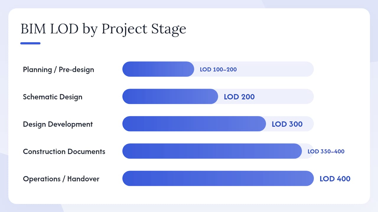
BIM responsibilities shift at each project stage. The table below maps typical engineer activities and expected deliverables from planning through operations.
| Project Stage | Engineer Activities | Key BIM Deliverables |
|---|---|---|
| Planning / Pre-design | Site analysis, feasibility modeling, program validation | Massing model (LOD 100–200), site constraints model, initial quantity estimates |
| Schematic Design | Structural system selection, civil alignment options, MEP zoning | Discipline models (LOD 200), clash-free coordination model, parametric option studies |
| Design Development | Detailed structural layout, MEP routing, civil grading | LOD 300 discipline models, coordinated federated model, updated quantity schedules |
| Construction Documents | Fabrication-level detail, connection design, specification linkage | LOD 350–400 models, IFC exports, COBie data population begins |
| Construction | RFI support, 4D sequencing, progress monitoring | 4D construction sequence model, clash resolution logs, as-built updates |
| Operations / Handover | Asset data validation, COBie handover, FM system integration | LOD 400 fabrication model, COBie spreadsheet, linked O&M documentation |
4D scheduling links model elements to a construction schedule so the team can visualize the build sequence and catch access conflicts before mobilization. 5D estimating connects model geometry to cost data, allowing quantity changes to flow automatically into budget updates. At handover, COBie-structured data gives facility managers the asset register, equipment schedules, and maintenance data they need without manual re-entry.
Three questions to ask at project kickoff
When you join a BIM project, three questions to the BIM manager or BEP document will clarify your responsibilities immediately:
- What LOD is required for my discipline at each exchange event, and what attributes must be populated? This defines your modeling scope and prevents over-detailing early.
- What is the CDE platform, and what are the workflow states and naming conventions I must follow? Uploading to the wrong folder or using a non-compliant filename breaks the coordination chain.
- What format must I export for federated clash detection, and who validates the export before submission? IFC export settings vary by software version; knowing the required schema and validation step up front avoids rejected submissions.
What standards govern BIM data exchange?
Standards define what information must be in a model, how it is structured, and how it moves between platforms. Three are non-negotiable for U.S. engineers working on projects with BIM requirements.
- ISO 19650. The international standard for managing information over the whole life of a built asset. Parts 1 and 2 cover concepts and the delivery phase; Part 3 covers operational phase. ISO 19650 defines the information management process, the roles of the appointing party and the appointed party, and the requirements for a CDE. Many U.S. federal and institutional owners now reference ISO 19650 in project information requirements.
- IFC (Industry Foundation Classes). The open data schema for exchanging BIM model content across software platforms. IFC is maintained by buildingSMART International and is the format required when models must move between, for example, Revit and Tekla or between a design team and a contractor using a different platform.
- COBie. A subset of IFC data organized into a spreadsheet-compatible format for asset handover. COBie captures equipment type, location, manufacturer, model number, warranty, and maintenance schedule data. Populating COBie fields correctly during design, not at handover, is the difference between a useful asset register and a manual re-entry exercise.
CDE minimum requirements
A functional CDE requires at minimum: defined folder structure and naming convention, workflow states (WIP, Shared, Published), access permissions by role, and a revision control protocol. Platforms like Autodesk Construction Cloud, Procore, and Trimble Connect all support these requirements. The specific platform matters less than whether the team has agreed on and documented the workflow before the first model is uploaded.
How to implement BIM on an engineering project
The table below provides a minimum viable roadmap from project kickoff to first federated coordination model. Each step includes the BEP items an engineer should own or verify.
| Step | Action | Engineer’s BEP Checklist Item |
|---|---|---|
| 1. Establish information requirements | Review client’s Employer’s Information Requirements (EIR) or project BIM requirements | Confirm LOD targets by stage, required attributes, and handover format (IFC, COBie) |
| 2. Draft or review the BEP | Confirm modeling responsibilities, exchange schedule, and naming conventions | Sign off on discipline LOD matrix; confirm CDE platform and folder structure |
| 3. Set up the authoring environment | Configure templates, shared coordinates, and reference model links | Verify project origin, units, and coordinate system match across all discipline models |
| 4. Author to LOD target | Model discipline elements to the agreed LOD for the current stage | Populate required attributes; do not model beyond the stage LOD |
| 5. Validate before exchange | Run internal clash check; validate IFC export against agreed schema | Confirm attribute completeness; resolve internal clashes before submitting to coordinator |
| — | Submit to BIM coordinator for federated model assembly | Attend clash review meeting; assign and track resolution of discipline-owned clashes |
| — | Incorporate clash resolutions; update model for next exchange event | Log changes in CDE; update revision status per naming convention |
| — | Populate COBie data; validate as-built model against site records | Confirm all required COBie fields are populated; submit final IFC and COBie to client |
Two contract clarifications to request before signing: first, confirm who holds liability for model errors used by other disciplines (this is not always the modeler’s discipline by default). Second, confirm the deliverable format explicitly — “BIM model” in a contract scope is not a deliverable specification. IFC schema version, LOD, and COBie sheet requirements must be named.
Common pitfalls and how to avoid them
Most BIM failures on engineering projects are process failures, not software failures. The patterns repeat across project types and firm sizes.
- Over-modeling. Modeling structural connections at LOD 400 during schematic design bloats file size, slows coordination, and produces detail that will change. LOD discipline requires modeling only what the current decision point demands. Define LOD targets in the BEP and enforce them.
- Late authoring. Starting BIM modeling after 2D drawings are already advanced forces a retroactive translation that introduces errors and misses the coordination value entirely. BIM must be the primary design medium from the start of design development.
- File bloat and performance degradation. Large linked model assemblies slow authoring tools. Mitigate with worksets, model subdivision by zone or level, and disciplined purging of unused families and views.
- Missing attributes. Geometry without required attributes (material, fire rating, manufacturer, maintenance interval) fails COBie validation at handover. Assign attributes during modeling, not as a handover cleanup task.
- Incompatible export formats. IFC exports from different software versions or with incorrect export settings produce models that lose geometry or attributes on import. Validate every IFC export before submitting to the coordination platform.
- BIM washing. A project that claims BIM compliance but lacks a CDE, a BEP, and validated data exchange is not delivering BIM. It is delivering 3D CAD with extra steps. BIM washing creates wasted effort during model transfers between platforms and gives owners no usable asset data at handover. Red flags: no named CDE platform, no LOD matrix in the BEP, and no IFC validation requirement in the contract.
For project managers: governance steps that reduce rework include a model audit at each stage gate, a defined clash resolution workflow with assigned owners and deadlines, and a COBie compliance check before the handover milestone.
How engineers can move upstream with BIM
The highest-value use of BIM for engineers is not documentation. It is early-stage influence on design decisions before cost and schedule are locked. BIM allows engineers to move upstream, using parametric models and early-stage optioneering to influence design before major cost commitments are made.
A practical upstream checklist for engineers:
- Author a parametric structural or civil model at LOD 200 during schematic design. Even a simplified model lets you run clearance checks, extract preliminary quantities, and test multiple structural system options against cost and constructability criteria.
- Run model-based trade studies before the design development gate. Compare two foundation systems, two framing approaches, or two alignment options using model-extracted quantities and schedule data rather than rule-of-thumb estimates.
- Co-author with the architect or civil lead from the start. Shared coordinates and a federated reference model established at project kickoff prevent the misalignment that forces rework at design development.
- Use parametric families or Civil 3D corridors to test sensitivity. Changing a single parameter (footing depth, road grade, column spacing) and observing the downstream effect on quantities and clearances is the core of model-based optioneering.
Consider a retaining wall design for a highway interchange. A civil engineer using Civil 3D can model three wall types (cast-in-place concrete, MSE wall, soldier pile) as parametric corridor components, extract material quantities for each, and compare them against a preliminary cost model within hours. The same comparison using 2D drawings and manual takeoffs takes days and is less accurate. The decision is made earlier, with better data, and the selected option carries through to construction documents without re-modeling.
Pro Tip: When running parametric optioneering in Civil 3D or Revit, lock your shared coordinate system and project origin before generating option variants. Misaligned origins between option models are the most common cause of incorrect quantity comparisons and federated model conflicts during early-stage coordination.
Key Takeaways
BIM for engineers is a data-driven process, not a software category, and its value is greatest when engineers engage with it at the earliest project stages using standards-compliant workflows.
| Point | Details |
|---|---|
| BIM is a process, not a tool | Governance (BEP, CDE) and standards (ISO 19650, IFC, COBie) determine whether BIM delivers value. |
| LOD discipline prevents waste | Model only to the LOD required at each decision point; over-detailing early slows coordination and increases rework risk. |
| Move upstream to capture value | Parametric optioneering at schematic design lets engineers influence cost and constructability before commitments are locked. |
| Validate IFC exports before submission | Unchecked exports lose geometry and attributes; validate against the agreed schema at every exchange event. |
| Certifications accelerate career growth | Autodesk Certified Professional and buildingSMART openBIM credentials are recognized by U.S. employers and support salary progression. |
A practitioner’s view on what BIM actually changes
The most significant shift engineers describe after adopting BIM is not the software. It is the change in when decisions get made.
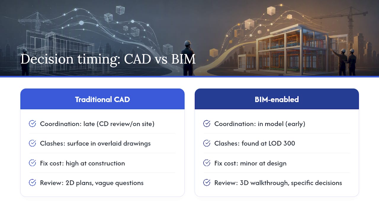
In a traditional CAD workflow, coordination happens late, typically during construction document review or, worse, on site. Structural, MEP, and civil disciplines each produce drawings in relative isolation, and conflicts surface when the drawings are overlaid manually or when a contractor flags a conflict during submittal review. By that point, the cost of a change is an order of magnitude higher than it would have been at schematic design.
BIM moves that coordination to the model. Clash detection in Navisworks or Revizto surfaces conflicts at LOD 300, when geometry is defined but fabrication has not started. An MEP duct routing through a structural beam web is a 15-minute model fix at design development. The same conflict discovered during steel erection is a field modification, an RFI, a potential schedule delay, and a cost change order.
What engineers also report, though it gets less attention, is the change in design review quality. When a client or contractor can walk through a 3D federated model rather than interpret 2D plan and section drawings, the questions they ask are more specific and the decisions they make are better informed. That shift in review quality reduces the late-stage scope changes that consume engineering hours without adding project value.
The challenge is that BIM’s upstream value requires upstream investment. A parametric model at LOD 200 takes more setup time than a 2D schematic. That investment pays back during coordination and construction, but it requires a project structure and a client willing to fund early-stage modeling. Engineers who understand how to make that case, and how to structure a BEP that captures the value, are the ones who get the most out of BIM on real projects.
Authoritative sources for further reading
Engineers looking to build BIM competency or verify project requirements should go to primary sources, not secondary summaries.
- What Is BIM | Building Information Modeling | Autodesk
- Building information modeling
- An introduction to Building Information Modelling (BIM) — Institution of Structural Engineers
- CRSI BIM Engineer-Architect benefits insert
- Autodesk — BIM for structural engineering
- Building Information Modelling for Engineers: The Ultimate Guide
- Bim Engineer Salary: Hourly Rate February 2026 USA - ZipRecruiter
For plumbing and MEP coordination specifically, model-based documentation and attribute data support the same COBie handover requirements that apply to mechanical and electrical systems. Engineers specifying plumbing fixtures and systems for BIM projects can find product specifications and technical data at Santehnikasveikals, covering faucets, drainage, heating systems, and installation accessories relevant to MEP model content.
Recommended
- Step by Step Interior Plumbing Design for Homeowners | Santehnikasveikals.lv
- Why Comply With Plumbing Standards: A 2026 Guide | Santehnikasveikals.lv
- Water Supply Planning Guide for Homes and Businesses | Santehnikasveikals.lv
- Cost-Saving Plumbing Ideas That Actually Work in 2026 | Santehnikasveikals.lv
Оставьте комментарий